Building a Solar-Powered Meshtastic Node
I've been playing with Meshtastic for a couple of years now—mostly experimenting with portable nodes, MQTT gateways, and coding some bots.
More recently, I've been helping out with ERSN.net (Ebbetts Radio Safety Net), and we've been exploring how Meshtastic could supplement the existing GMRS radio coverage. We've identified four summit locations that would be ideal for permanent nodes—and that gave me the push I needed to finally figure out how to build a solar node from scratch.
Each one cost me about $120 in parts—though with a bit more planning and less reliance on Amazon, I think that could be trimmed down. In this post, I'll walk through the full build: what I used, how I assembled it, and some photos. There's also a full parts list with links if you want to build your own.
Parts List
Here's everything you need to build one node. I've included Amazon links for convenience, but you might find better prices elsewhere.
| Item | Per Unit |
|---|---|
| RAKwireless StarterKit | $34.97 |
| Soshine 6W mini solar panel | $11.49 |
| Omni 5dBi gain antenna | $12.49 |
| Bluetooth antenna | $4.75 |
| IPEX to N Type cable | $4.50 |
| Battery 10000mAh | $20.00 |
| M4×8 Screws | $1.05 |
| Breather Plug | $5.49 |
| Enclosure | $16.99 |
| Camera pole mount | $8.99 |
| Total per node: | $120.72 |
Optional Parts
| Item | Per Unit |
|---|---|
| Silicon sealant and adhesive | $5.99 |
| B-Connector wire crimps | $0.20 |
| Low voltage wire connectors | $0.92 |
| Silicon sealing tape | $2.39 |
Alternative Parts
| Item | Per Unit |
|---|---|
| ALFA Network 5 dbi Omni Outdoor Mini Antenna | $17.97 |
| RAIGEN 5.8 dbi 20in antenna | $31.95 |
| Pole mounting bracket w. U clamp | $9.99 |
| Heavy duty pole mount bracket (<50mm) | $9.99 |
I designed and 3D printed an enclosure insert that holds the battery and wisblock chip in place. The insert is not strictly necessary, but it does help keep things tidy. If you want to print your own, you can find the files here:
The model is also available on Printables.
Tools You'll Need
Nothing too exotic—most of this can be done with basic workshop tools:
- Drill with bits
- Dremel for cutting the enclosure and expanding antenna holes
- Marker or pencil for marking
- Ruler or measuring tape
- Screwdrivers
- Wire strippers
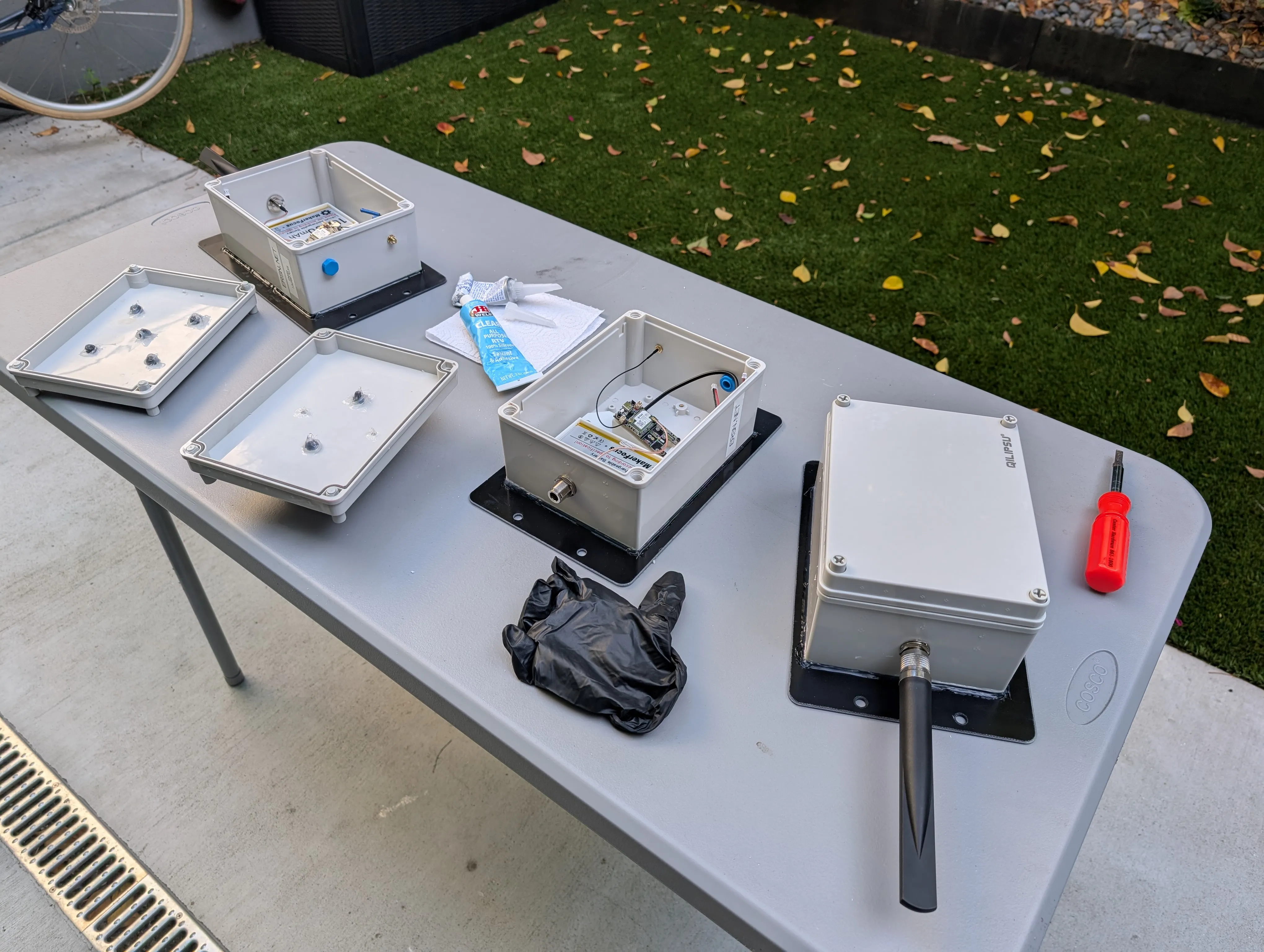
Build Guide
The build breaks down into four main phases: modifying the enclosure, attaching the solar panel, assembling the internals, and mounting. The whole process took me 3 hours to make 4 nodes. But I think next time it could be done in 30 minutes.
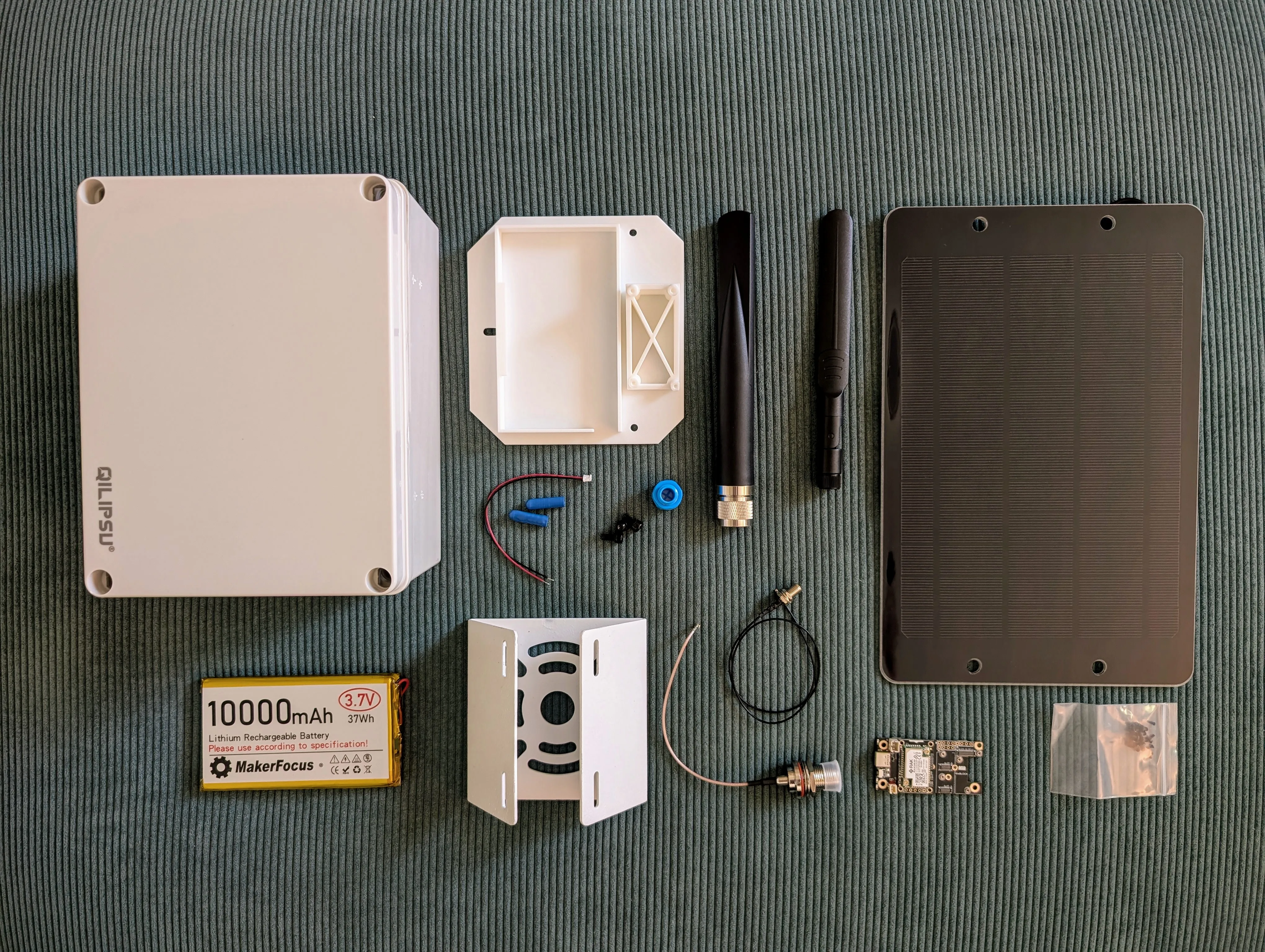
Component list : All components laid out including weatherproof enclosure, solar panel, Meshtastic board, 10000mAh battery, antenna, cables, and hardware
Enclosure Modification
The plastic enclosure needs a window for the solar panel and three holes: one for the LoRa antenna connector, one for the bluetooth antenna, and one for the breather valve.
The solar panel window can be 2" wide, then 1.5" above center and 1" below center. Make sure to get the orientation right. I used a Dremel with an EZ476 cutting wheel. Even with the wheel designed for plastic, it still melted the plastic and got a bit messy, but the edge is hidden by the solar panel and the insert, so it doesn't matter too much. I removed any sharp edges with a file.
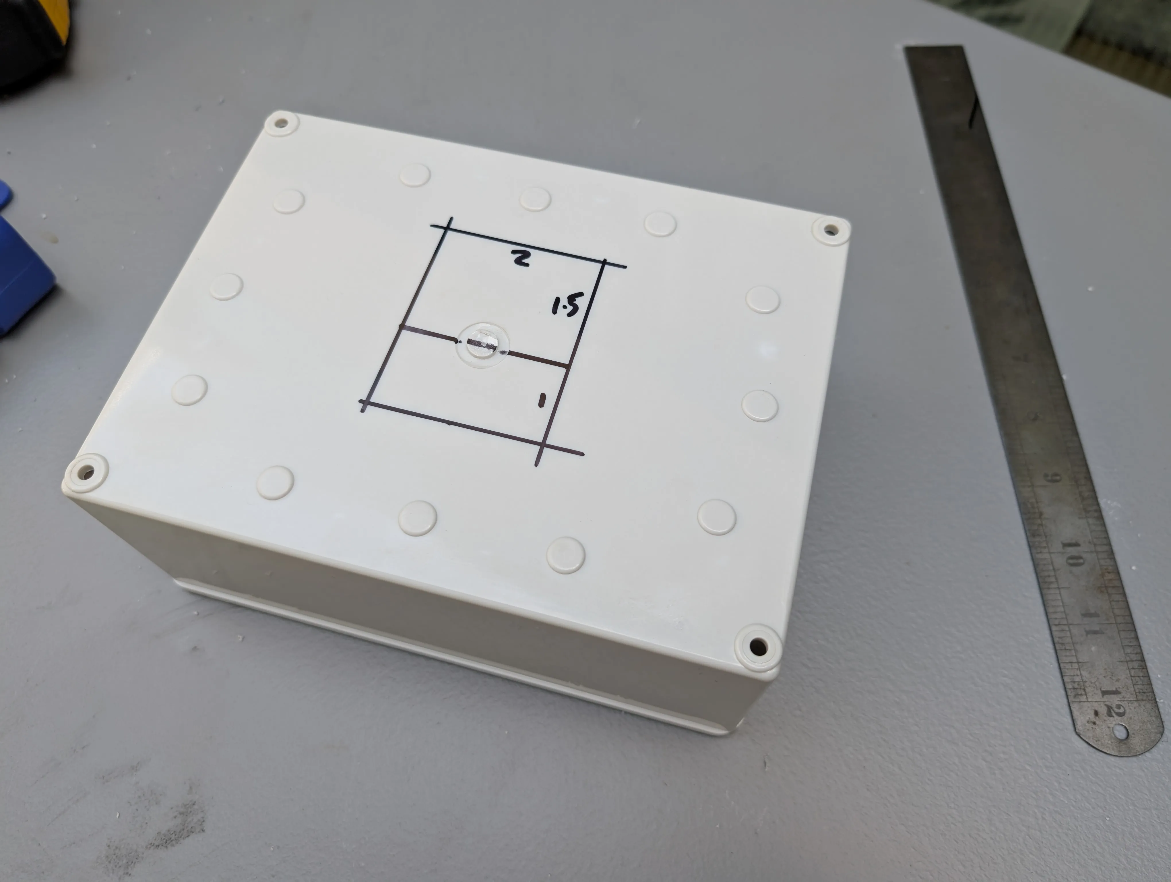
Enclosure Modification Planning : Marking measurements on enclosure lid for cutting
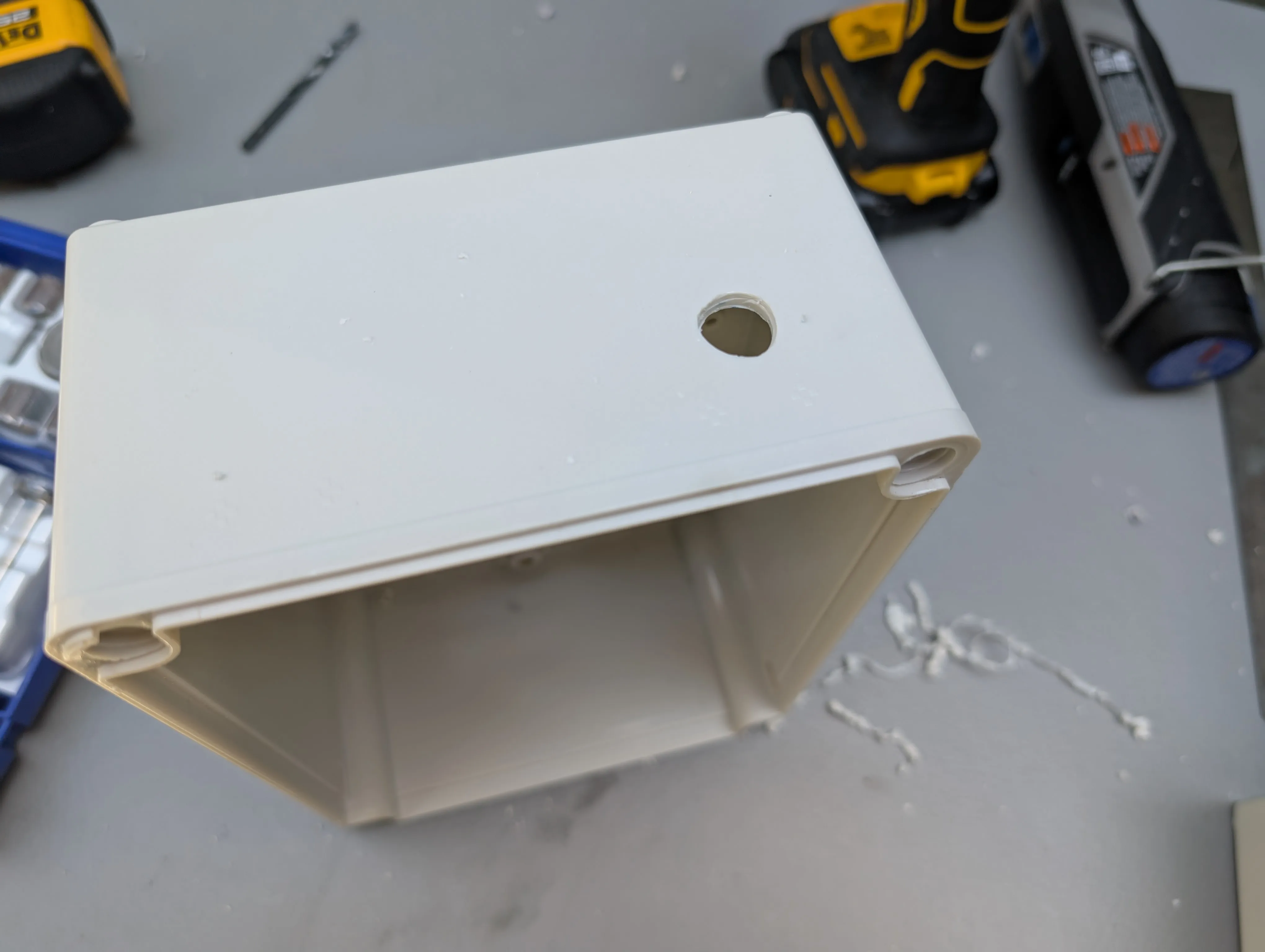
For the holes, I'd recommend using a stepped drill to get cleaner results. I used regular bits for the small holes and a rebar drill for the larger one—it's just what I had available. I then used the Dremel with a file tip to expand the hole until it fit the N-Connector. This actually worked out well, as it allowed me to create a hole that wasn't perfectly round which helped keep the connector in place. The SMA connector needed about a 6mm hole, and the breather valve was around 12mm.
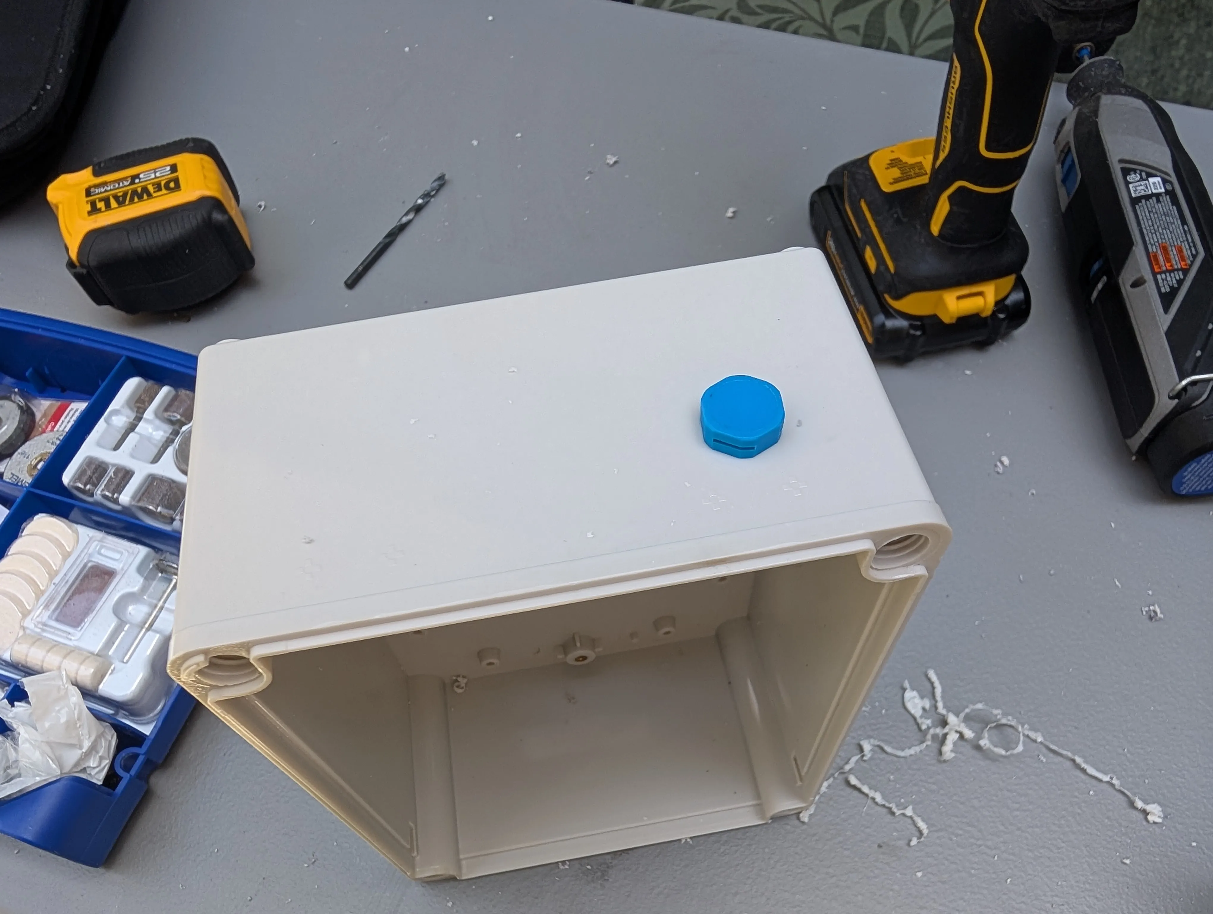
The breather valve allows air pressure to equalize while keeping moisture out, which may also not be 100% necessary, but I wanted to be safe. It also helps prevent condensation inside the enclosure.
You can use an internal bluetooth antenna—the RAK boards come with a flat PCB antenna—if you don't want an extra hole, but I figured the extra bluetooth range would be useful.
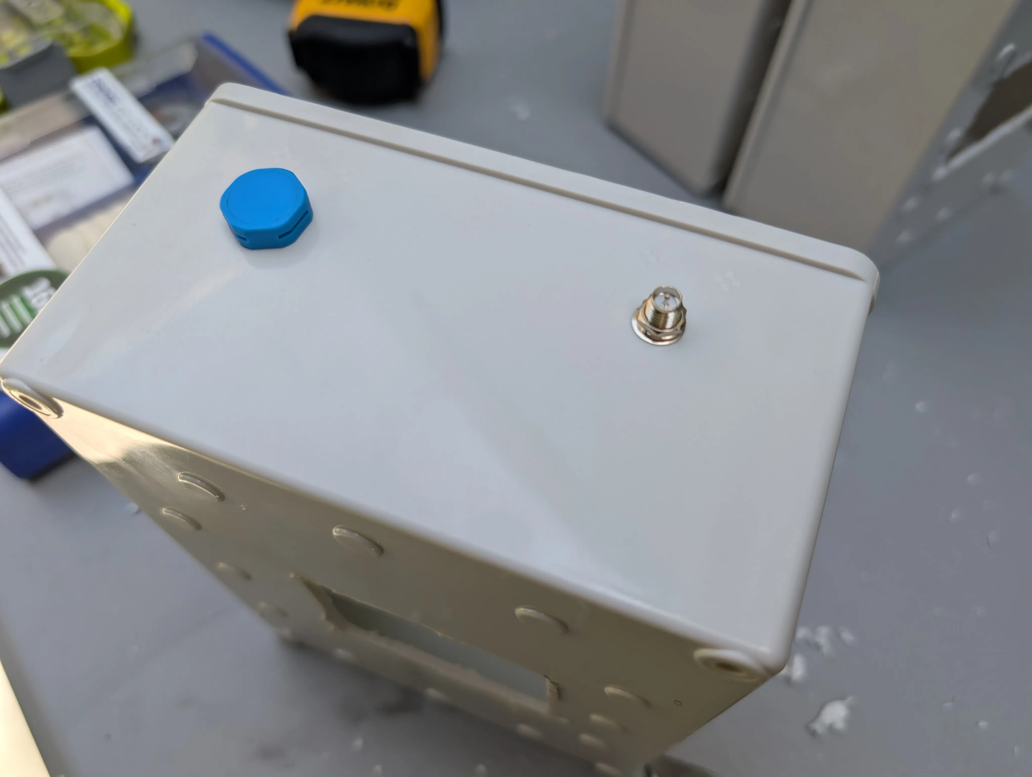
Antenna Mount and Breather Valve : SMA antenna connector installed in enclosure lid for external bluetooth antenna
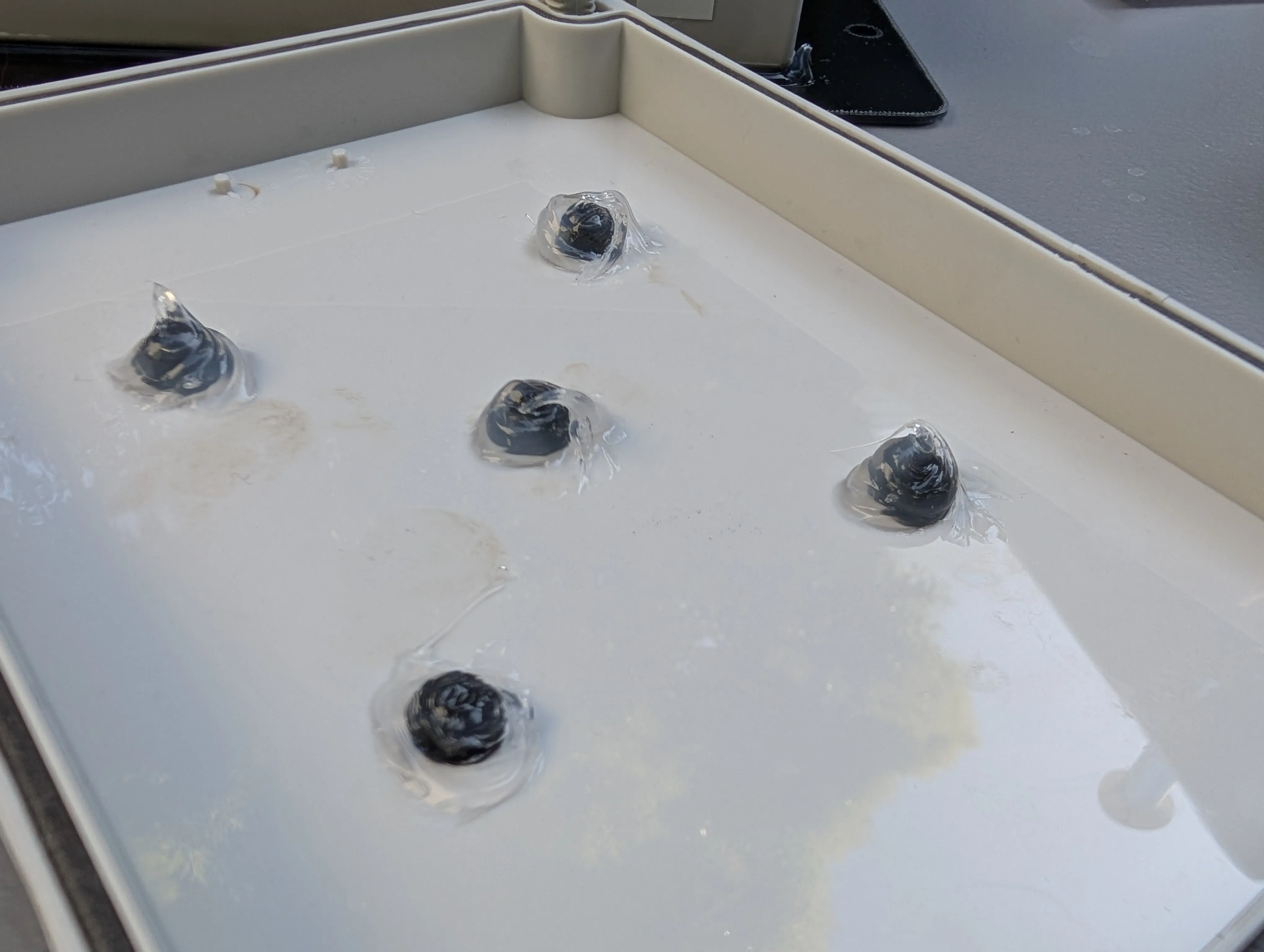
Attaching the solar panel
The next step was to attach the solar panel to the enclosure. I decided to keep the whole node as a one-piece, instead of having a separate solar panel that could be mounted elsewhere. This way, I can just mount the whole thing on a pole or post. The Soshine 6W panel is small enough that it fits nicely on the enclosure.
I used silicone adhesive to attach the panel, first applying a bead to each of the bumps you can see on the base of the enclosure, and then creating a complete seal around the window and the edge of the panel.
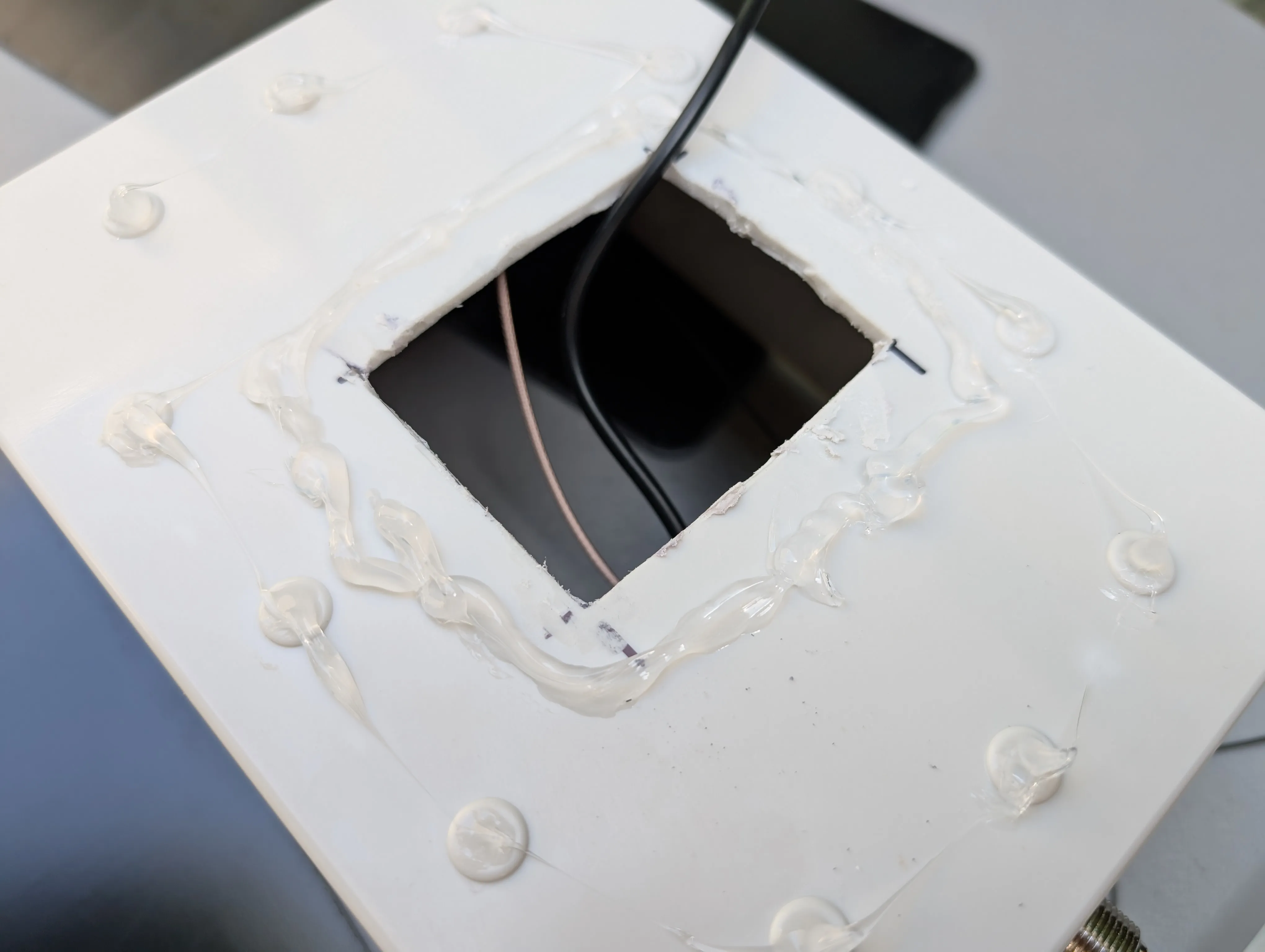
Sealing the solar panel : Underside of enclosure showing solar panel attached to the window cut in the enclosure
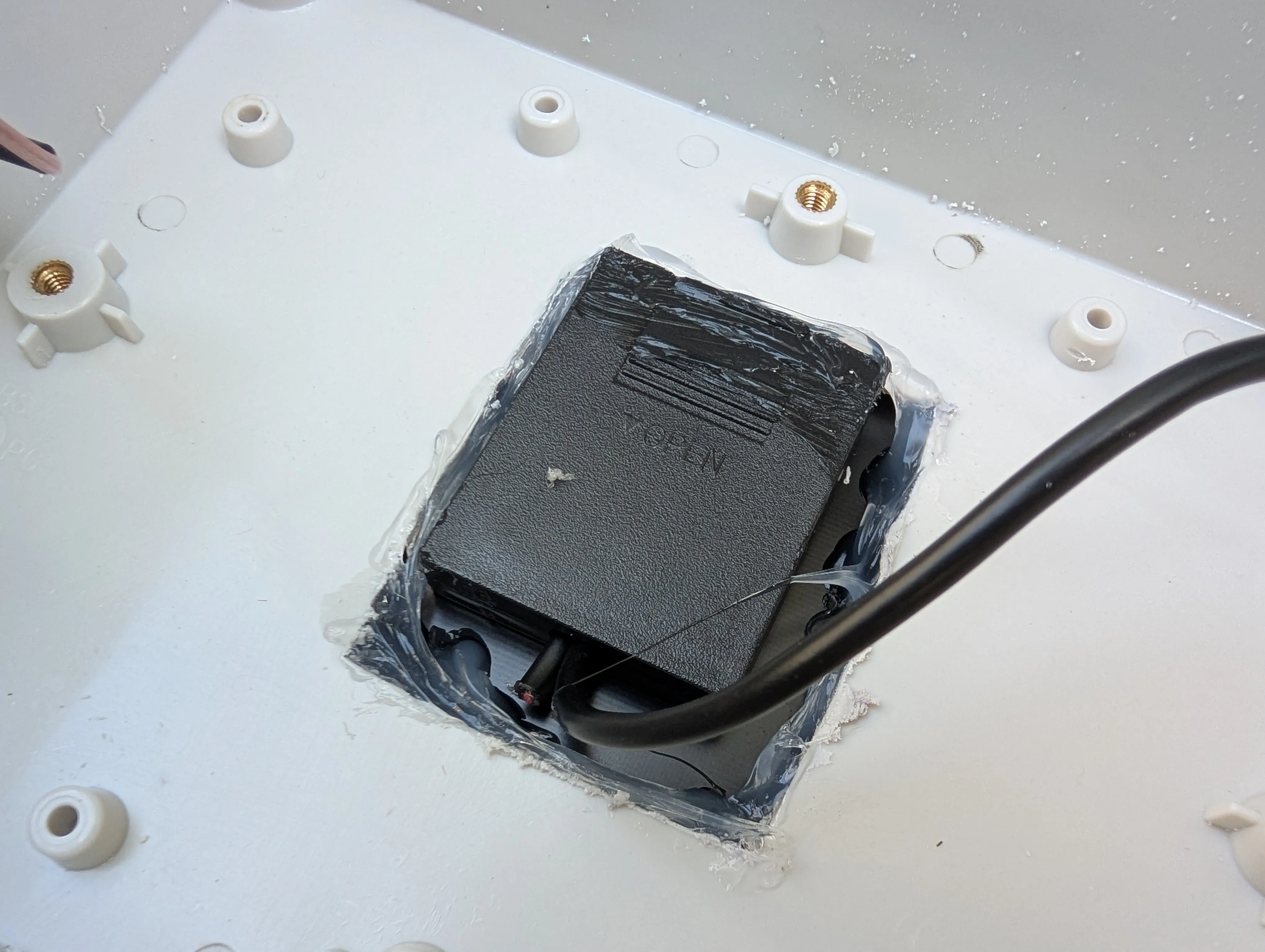
You'll notice I cut off one of the cables from the solar panel. This one is used to connect multiple panels in series, which we don't need.
Assembling the internals
As I mentioned above, I used a 3D printed insert that I designed to work with this enclosure. It holds the battery and the Meshtastic board in place, and angles the board to make the USB port more accessible.
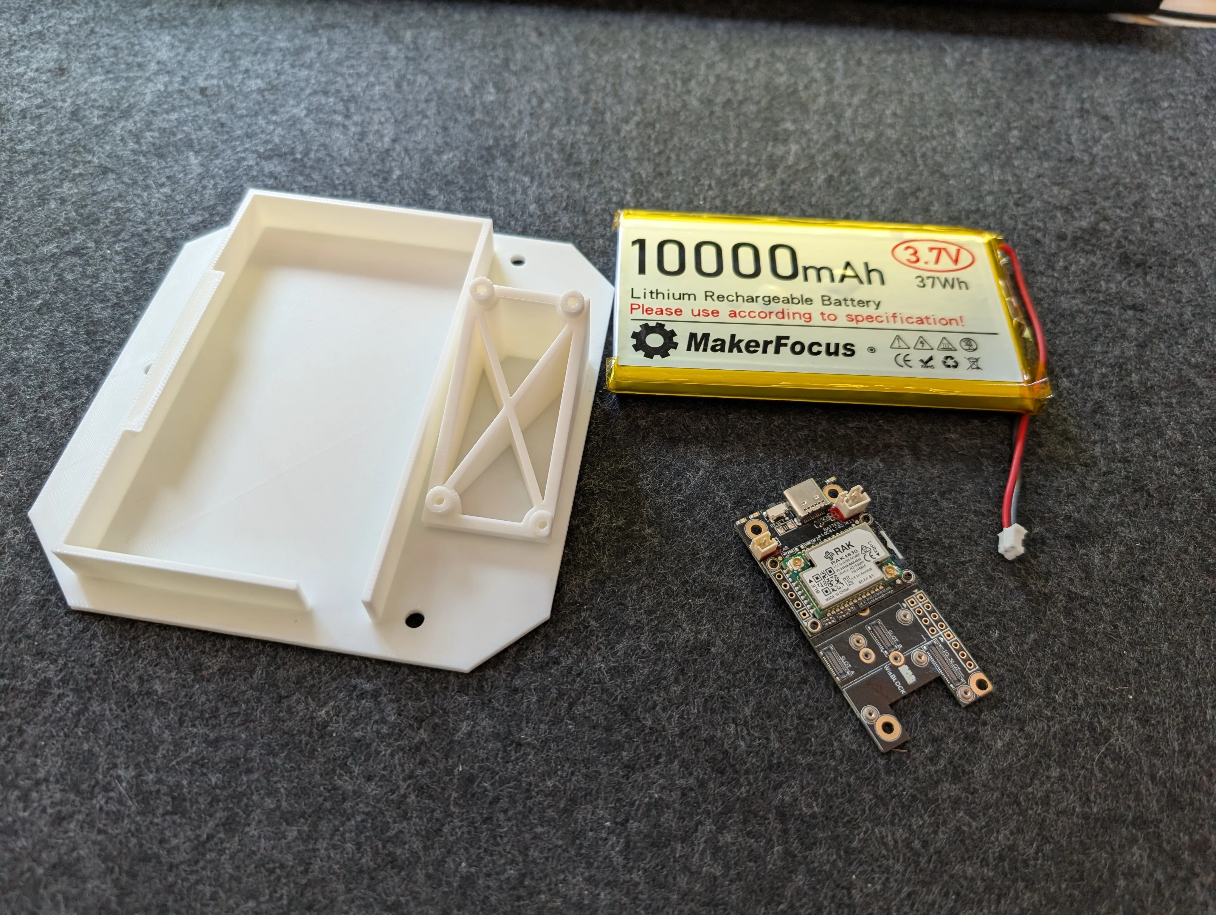
Battery and Board Configuration : 10000mAh MakerFocus battery positioned next to Meshtastic board and enclosure insert
The 10,000mAh battery is a bit overkill. It loses only about 1% per day with no sunlight, so it can likely last months without needing to be charged. But our plan is to deploy these nodes in remote locations, where they will get covered in snow for potentially weeks at a time, so I wanted to make sure they had enough capacity to last through the winter. If you want to save some money, you could use a smaller battery like a 3000mAh.
I mounted the Meshtastic board first, using the screws that come with the board. The battery fits nicely alongside it.
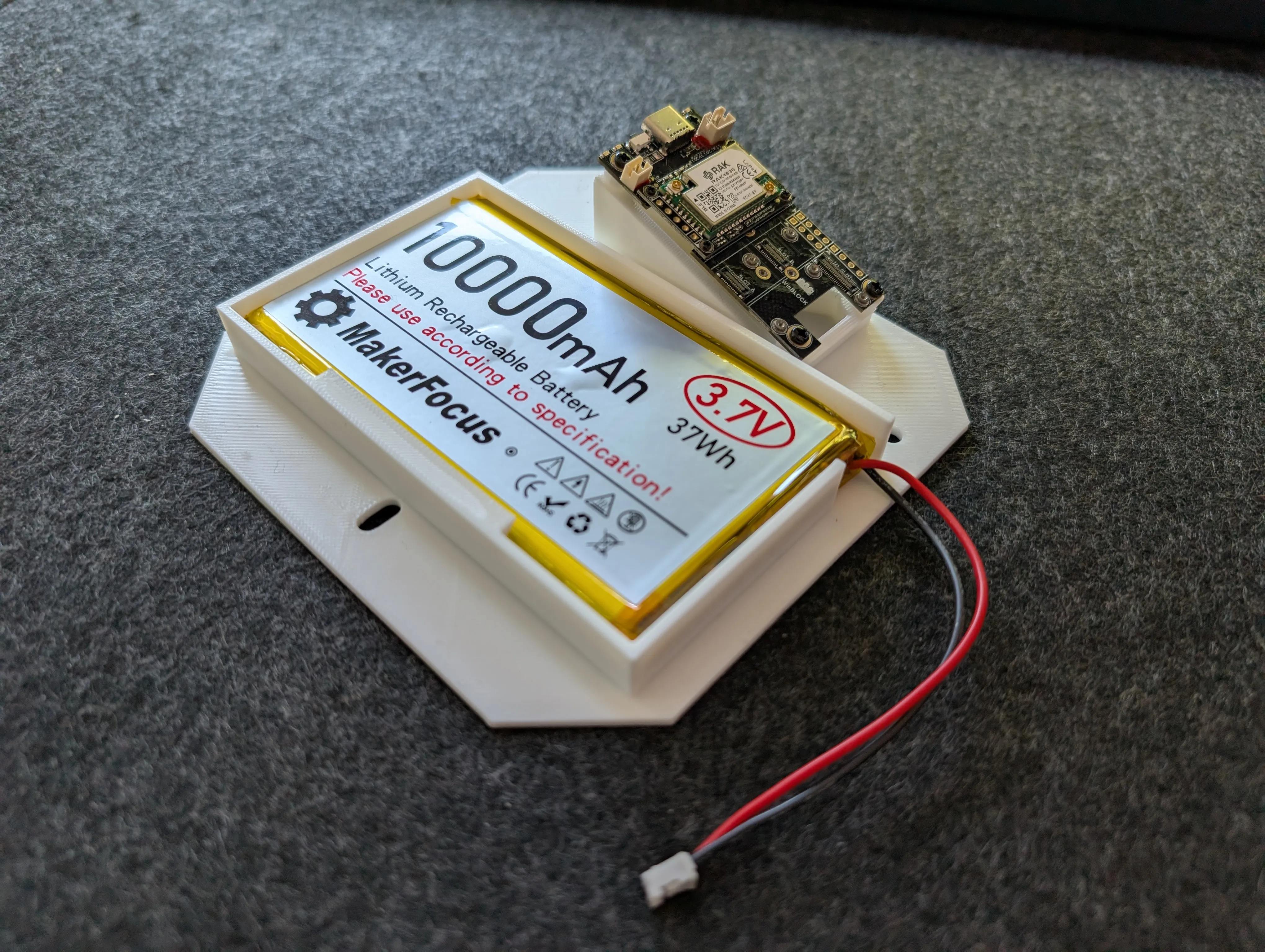
Enclosure Insert : Close-up of enclosure insert with chip mount and battery caddy
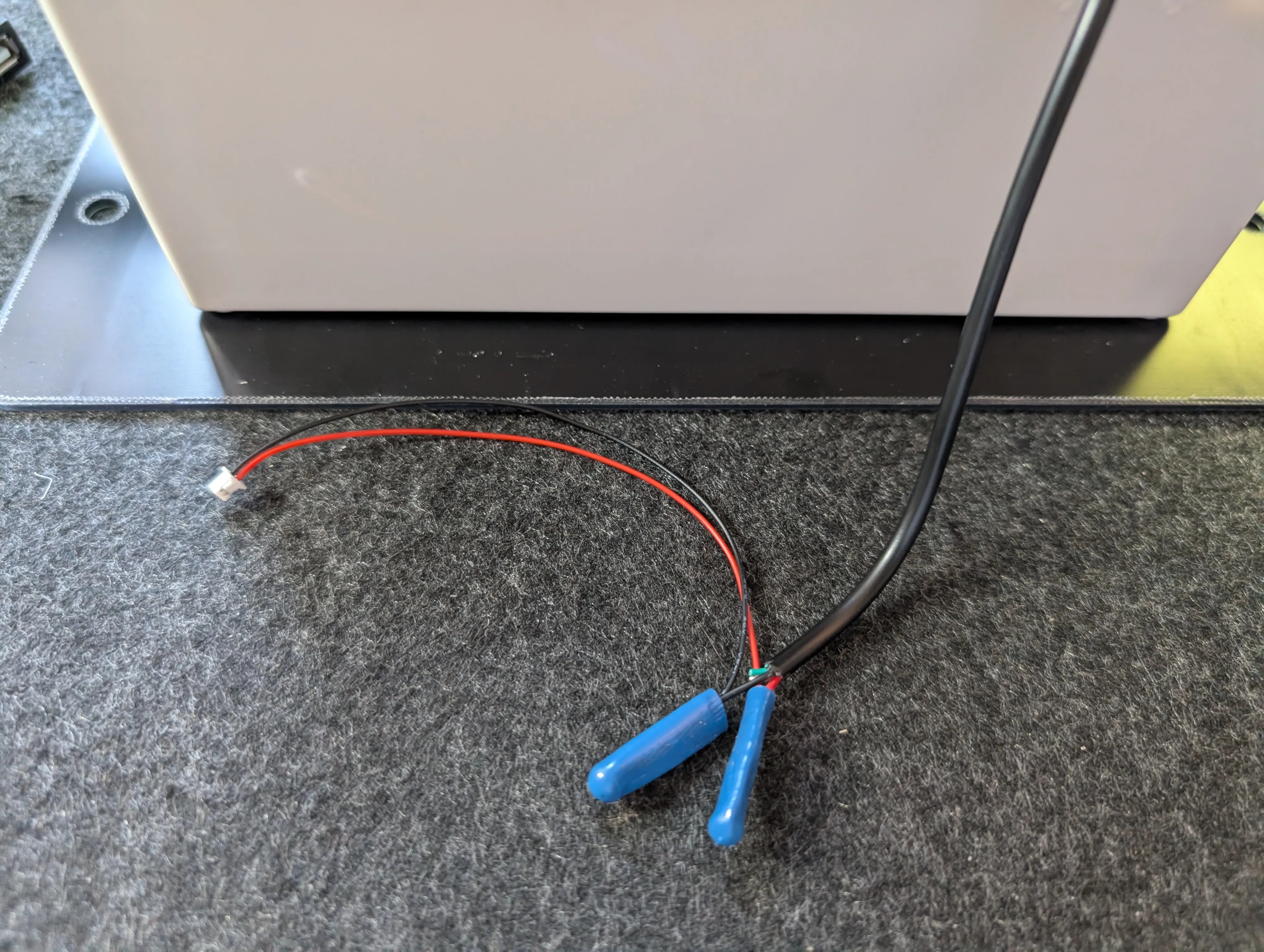
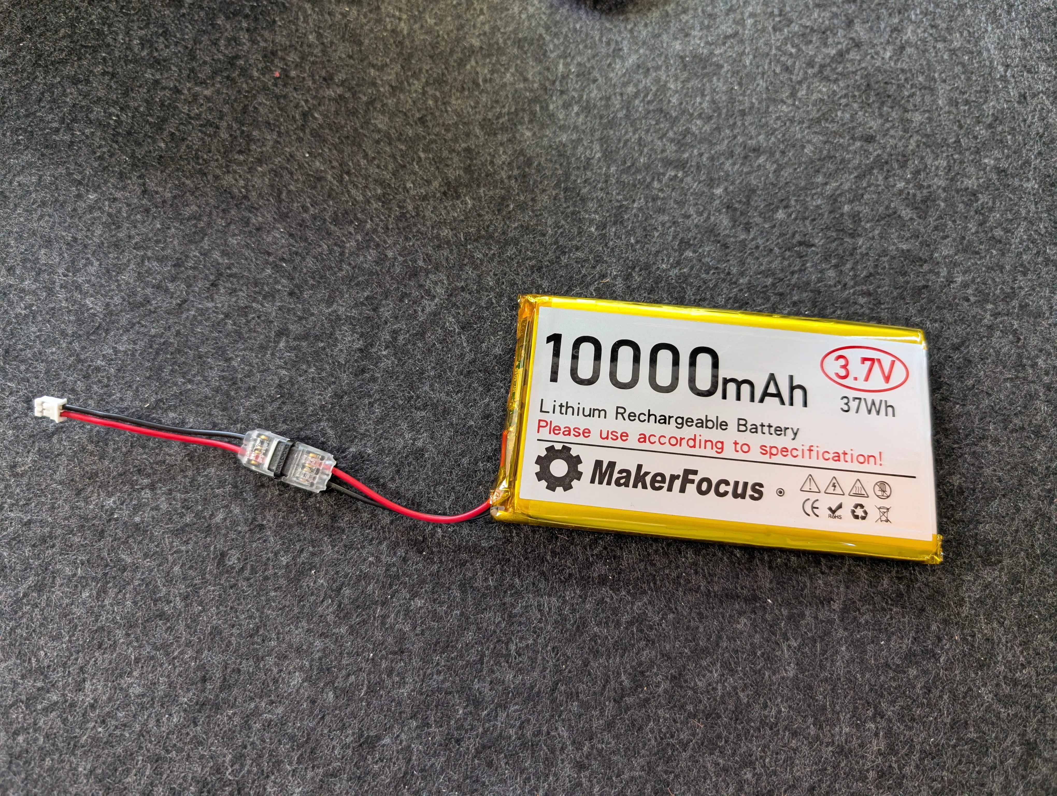
The RAK board should have come with a JST connector for solar charging. To connect it, I cut the solar panel's USB cable and connected to the positive (red) and ground (black) wires. The green and white wires are not used in this setup, so I cut them off. I had some B-Connectors available, but twisting, soldering, and taping would be fine.
IMPORTANT #1! In the second picture above, you'll notice that I cut and then inverted
the positive/ground cables. This is because the polarity of the battery is reversed compared to
the RAK board. Check your battery and look for the + symbol on the board to make sure
yours match.
IMPORTANT #2! Do not connect the battery to the board until you have the antenna connected. The board will try to transmit without an antenna, and that can damage the radio.
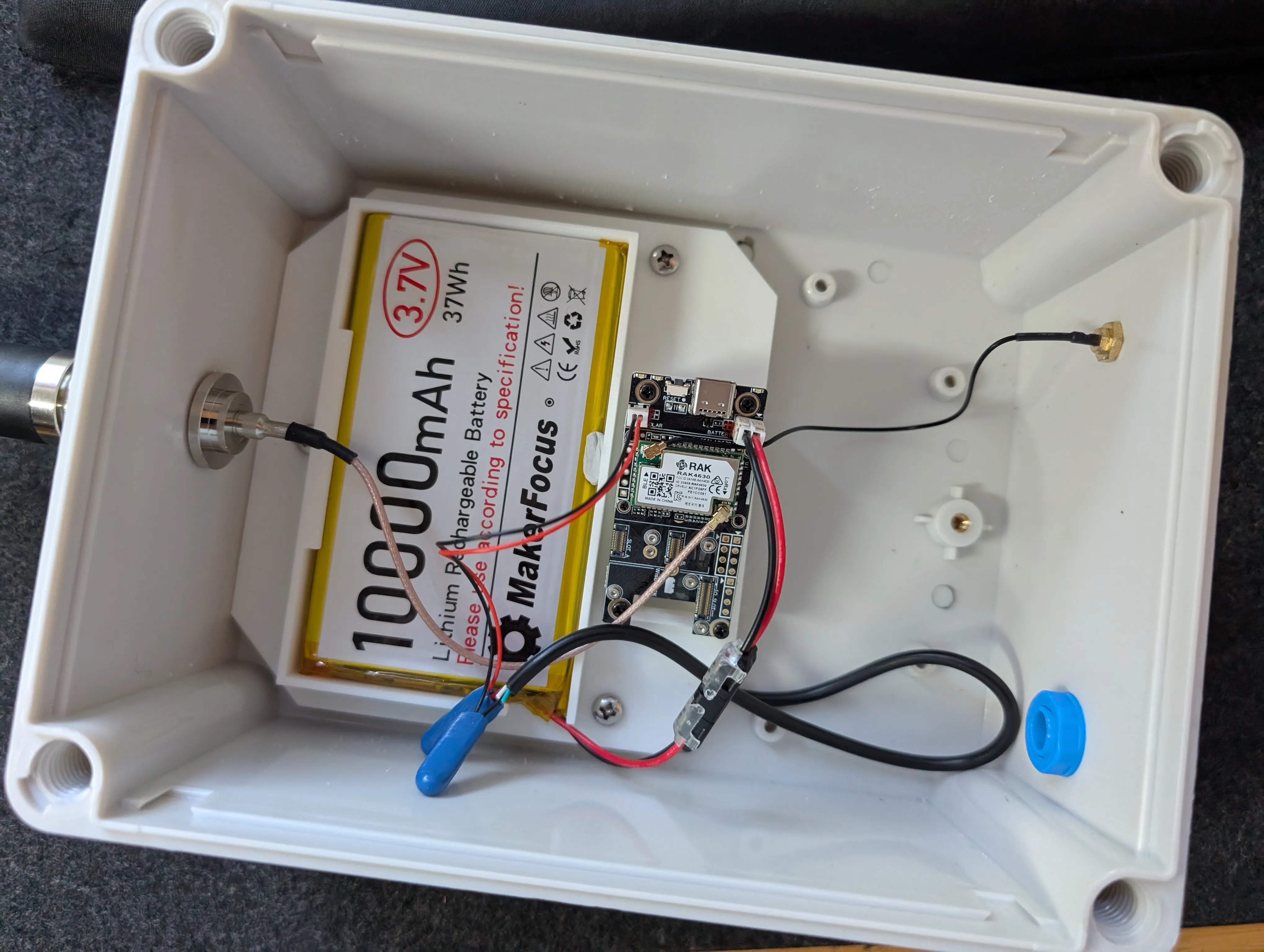
Final Component Check : Final verification of all internal components before sealing enclosure
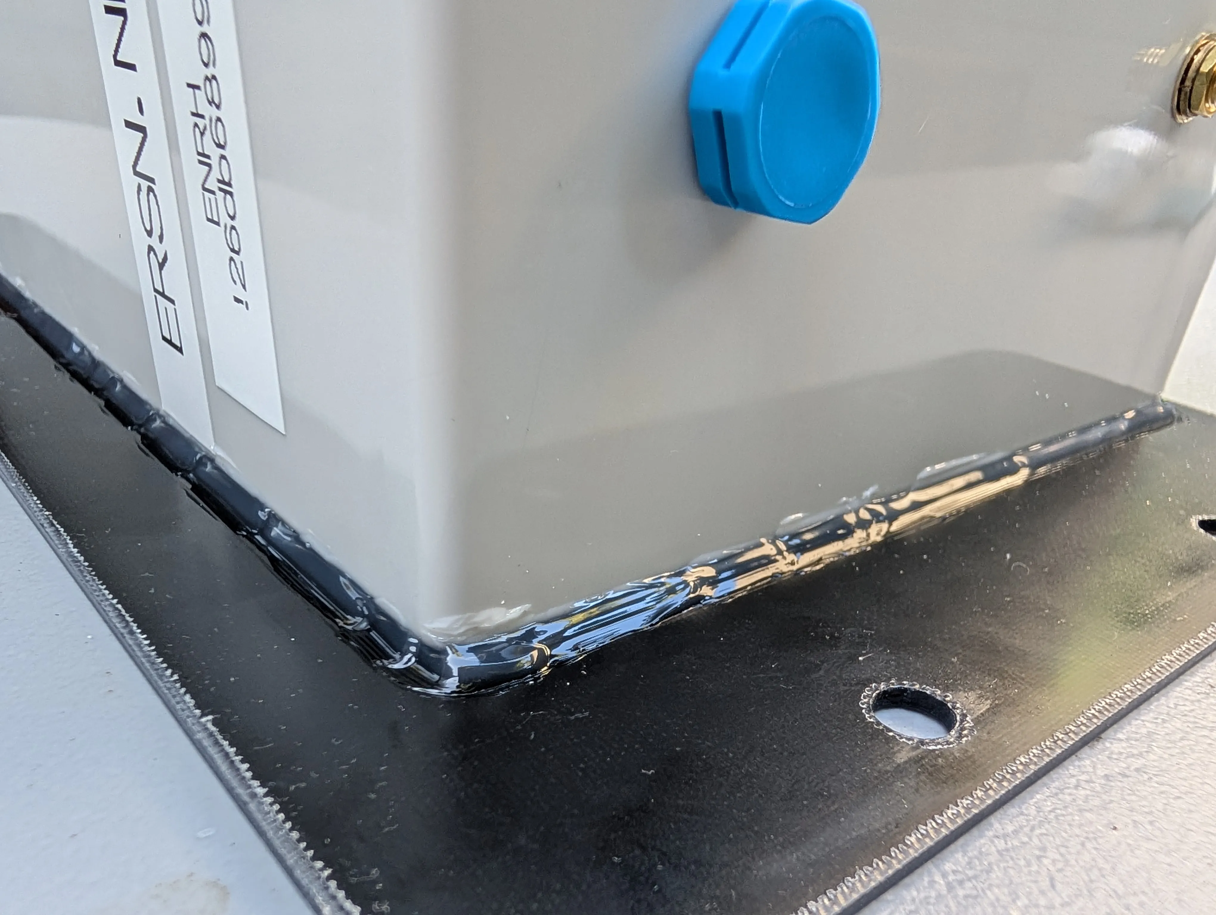
Mounting hardware
Since I was building 4 nodes, I decided to experiment with different mounting methods. I'll need to report back on which worked best. But broadly speaking, the approach was all the same:
Drill 4.2mm holes and then screw in M5 bolts with washers and nuts. Then use silicone sealant to cover the holes.
Final Testing
Before deploying the nodes in their remote locations, I wanted to make sure everything was working well, so I left them in a sunny spot for a couple of days and monitored the discharge and charge cycle. I also tested the waterproofing by spraying with a hose.
For final deployment, I plan to use silicone tape around the antenna connector joints and the seam of the box. We'll need to remove it before doing firmware updates, but that won't be too often.
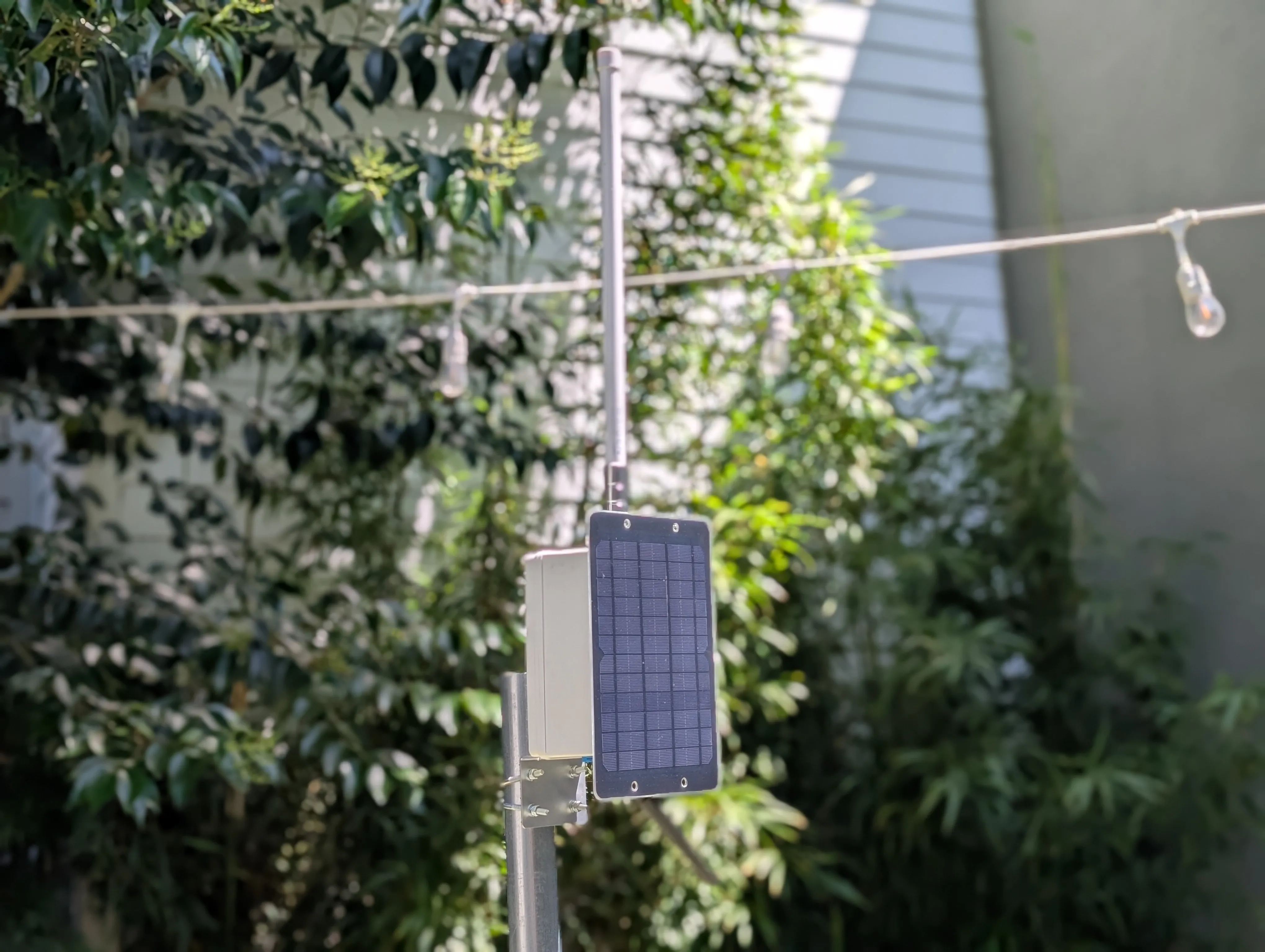
Test Installation : Completed solar Meshtastic node installed outdoors on pole mount with solar panel and alternative RAIGEN antenna
Next Steps
If you build one of these, I'd love to hear how it goes. There's always room for improvement—better antennas, larger solar panels, different enclosures. But this basic design has proven reliable enough that I'm comfortable deploying them in remote locations.
Edit: Battery Choice for Extreme Temperatures
A few people have asked about battery choices. I'm not an expert, but I did some research to help guide decisions. If you're deploying nodes where interior enclosure temperatures might drop below -10 °C (14 °F) or rise above 60 °C (140 °F), the LiPo battery I used may not be ideal.
LiPo batteries degrade faster in high heat—potentially losing 20–30% of capacity over a single summer if kept fully charged in hot conditions. They also shouldn’t be charged below 0 °C (32 °F). That said, the RAK board uses low-current charging (~350 mA), which may reduce stress when charging near or slightly below freezing.
A good alternative is using cylindrical Lithium-Ion cells like 18650 or 21700 (e.g., Molicel P42A). These cells tolerate a wider temperature range—from around -20 °C (-4 °F) up to 60 °C (140 °F). Just be sure to include a protection circuit (either built-in or external) to manage overcharge, over-discharge, and short circuit conditions.
LiFePO₄ (Lithium Iron Phosphate) batteries are another option with excellent thermal stability and longer lifespan. However, they’re bulkier and require a different charging profile (max 3.65 V), which isn’t supported by the RAK board’s internal charger. You’d need an external charge controller if you go this route.
Other recommendations include insulating the interior with foam to reduce rapid heat gain or loss, avoiding wall-mounting on sun-heated surfaces, and raising the enclosure to allow airflow underneath. If mounting in direct sun, consider using a white or reflective enclosure to reduce internal temperatures.